
Build your Pocket Tracker
To build your Pocket Tracker, first of all you need the electronics and it’s possible to buy the board on Elecrow Store.
Once you have it, there are two ways to get started with your Pocket Tracker: build the case yourself or order a full kit that includes high-quality 3D-printed parts from me directly.
On this page, you’ll find all the information you need to assemble your PocketTracker — from component sourcing and 3D printing files to wiring guides and software setup. So let’s get started!
Build Yourself
This section is for who own a 3D printer and want to build and assemble everything. Of course it can be the hard path but also it can be a lot of fun. First of all you need the stl files, so download everything at this link.
Materials List & 3D Printing Tips
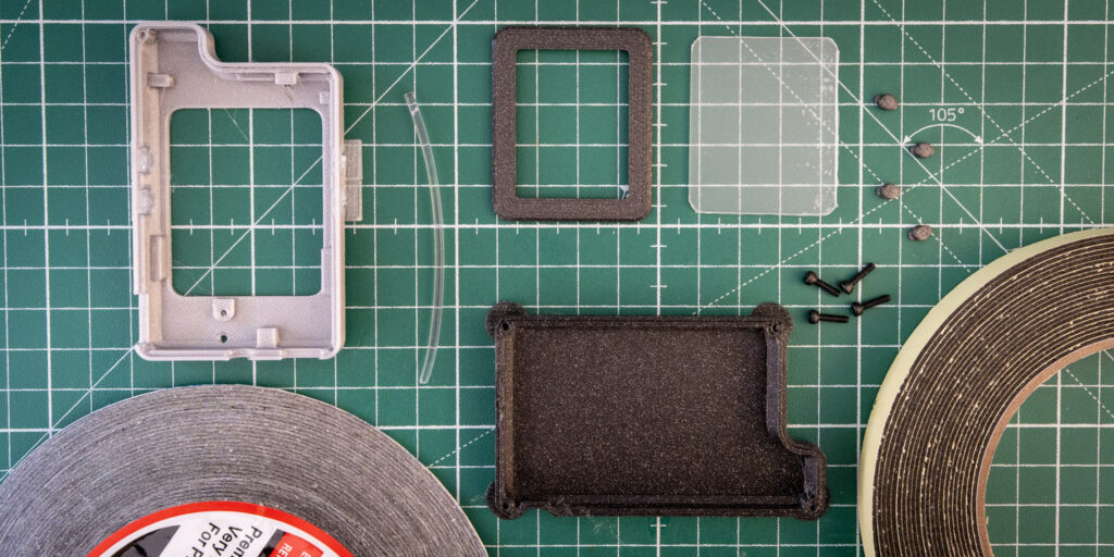
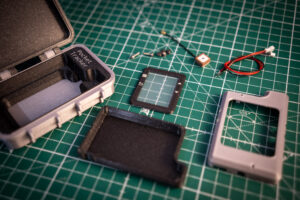
Here’s what you’ll need to build the physical parts:
- 1mm thick transparent polycarbonate sheet (for the screen protector)
- Ultra-thin double-sided tape (1mm wide)
- 1mm thick foam adhesive tape (for display protection)
- Flexible optical fiber/guide – 2mm diameter (for LED diffusion)
- Antenna – [YCGO004AA]
- Battery – [LP674261] [LP503759] [L653454] [LP654060]
- Battery connector (compatible with your battery choice)
- MicroSD card – Suggested: 32GB, formatted FAT32
- M2 screws (x4), length 8mm hex head with Allen socket
I personally used the following print settings with good results:
- Layer height: 0.2mm
- Nozzle size: 0.4mm
- Supports: Everywhere – this helps with overhangs and tricky geometry
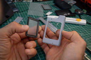
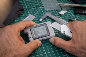
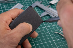
Depending on how well-calibrated your printer is, you may need to slightly tweak the holes or file down edges for a perfect fit. After a bit of cleanup and support removal, your part should look something like the following image.
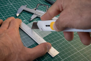
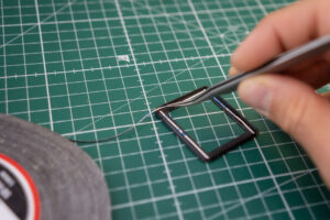
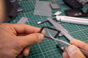
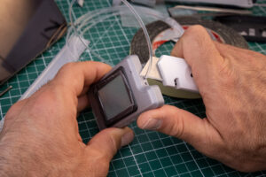
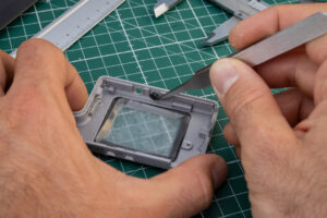
Assembling the Front Section
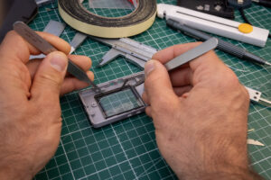
One of the most delicate parts is the display protection. You’ll need to cut a thin rectangle (35mm X 42mm) from the 1mm polycarbonate sheet to fit the front window. It’s easier than it sounds: Score the plastic with a sharp cutter, along a straight line, and repeat a few times—then gently snap it by bending.
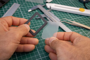
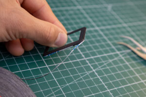
To attach it:
- Use ultra-thin double-sided tape (1–2mm wide)
- Align it carefully on the inside of the 3D printed front frame
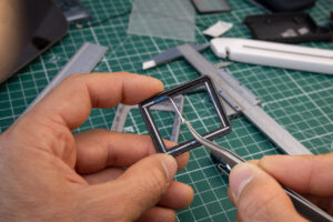
Next, you can either use adhesive tape to attach the display to the front frame or glue it directly.
To avoid damaging the display, add small strips of foam adhesive around the edges of the polycarbonate on the inside. This holds the display gently in place and acts as a shock absorber.
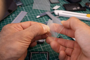
Too finish the front section, insert the 2mm flexible optical fibers:
- Into the two small holes on the front face (for status and charging LEDs)
- Into the hole on the side near the notch (for the high-intensity torch LED)
Make sure they:
Extend inward by a few millimeters to align with the LEDs
Sit flush with the surface of the 3D print
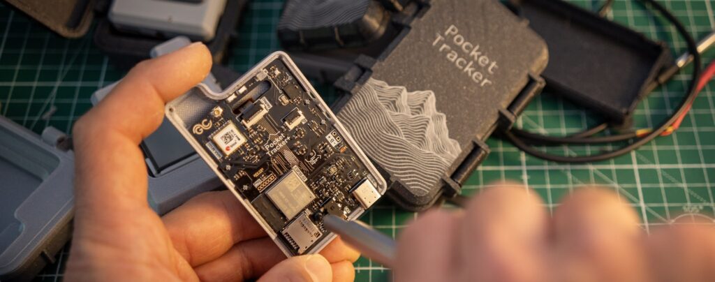
Electronics Assembly
If you already have the PocketTracker electronics module with the display, good news—your display should already be attached to the PCB using an M2 screw, 6mm long. If your screw is not M2 x 6mm, replace it. The front 3D printed part is specifically designed to fit that screw size. Before mounting the electronics into the 3D printed shell, solder the battery connector to the PCB. I used a Molex PicoBlade 1.25mm connector, but any compact connector will do. There’s limited space inside the case, and a long cable may interfere with battery placement. Keep the cable short – around 2–3cm
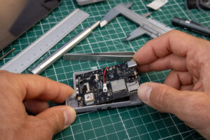
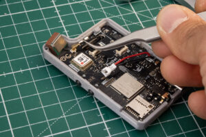
Mounting the PCB:
Before placing the PCB, you’ll need to position the pushbuttons into their dedicated holes in the 3D printed part. This can be tricky! The buttons are small, and they must be aligned and sitting properly in place. If they shift, the PCB won’t fit correctly.
- Start by inserting the top part of the PCB (the side with the high-intensity torch LEDs) into the frame.
- Then gently lower the rest of the PCB into position, at this stage, you might notice that the part with the screw is sitting slightly lifted. That’s normal.
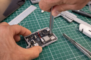
- Now loosen the M2 screw until the board lays flat inside the 3D printed part.
- Once aligned, tighten the screw again to secure the display and PCB firmly to the case
Press down gently on the PCB while tightening, making sure the display sits evenly on the foam tape without gaps.
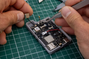
Attach the Antenna:
Now it’s time to install the antenna.
- Route the antenna cable underneath the PCB
- Pass it through the same hole used by the display’s flat flex cable.
- Fold it gently and connect it to the connector on the board.
The antenna cable is usually a bit stiff, but you can shape it with care to stay in place.
Use a small piece of foam adhesive tape to hold the antenna in place and prevent it from moving.
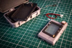
Final Assembly
You’re almost done! The last step is placing the battery inside the case and closing everything up. The enclosure is designed for compact LiPo batteries with a maximum size of: 6.7 × 42 × 61 mm. Make sure your battery fits within these dimensions for a proper closure. I’m using is this one [LP674261] and here is a list of compatible batteries: [LP503759] [L653454] [LP654060].
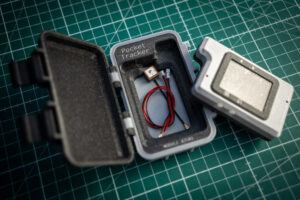
Secure the Battery:
To avoid the battery moving inside the case:
- Attach it with double-sided tape on the back side of the battery.
- If the battery is significantly smaller than the internal cavity, use adhesive foam or padding to fill the remaining space.
- Finally, close the back part of the enclosure using 4 M2 screws, 8mm in length.
That’s it! Your PocketTracker is now fully assembled and ready to join you on your adventures.

Build Your KIT
Each PocketTracker Kit is designed, 3D printed, engraved, and hand-finished by me, making every piece a little unique.
By purchasing the kit, you’re not only getting a ready-to-use, rugged 3D printed case custom-made for the PocketTracker—you’re also supporting the project directly. As a thank you, I include the complete enclosure, already assembled and fine-tuned for a perfect fit.
If you’re interested in buying the kit, just contact me [here], and don’t forget to mention where you’re located so I can provide an accurate price including shipping.
Materials List
What’s included in the Kit:
- All 3D-printed parts, reworked for a perfect fit
- Pre-cut adhesive tape for the display frame, already placed
- Pre-cut polycarbonate front cover
- Foam inserts included (ready to be placed)
- Antenna included
- Battery connector included
- All screws included
What you’ll need to add:
The Pocket Tracker kit is meant to make the build process easier and more enjoyable, without taking away the hands-on feel.
Many of the steps from the full DIY version are already done: the parts are 3D printed, engraved, and reworked by me, so everything fits nicely and looks clean.
The screen protection is already prepped with tape—just peel the film and place it. You’ll still need to solder the battery connector, which is included in the kit, and connect the antenna, also provided. The screws are all there too. The only thing you need to add is your own LiPo battery.
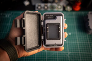
Each kit is individually numbered as MODULE #25XX—with “25” for the year and a progressive number after that—making every unit unique.
If you need more detail, you can follow the full assembly guide for the non-kit version. The steps are almost the same, just with a lot already taken care of for you.
I hope you enjoy the process, I’ve done my best to keep it simple, while keeping the fun and character of building something yourself.
Run It or Hack It
When your Pocket Tracker arrives, it’s almost ready to go out of the box — no complex setup.
The device comes pre-flashed with a factory test firmware, so you don’t need to run any test procedures — it’s already been tested and verified. You just need to flash the Pocket Tracker Firmware.
To start using it:
- Power it ON by pressing and holding the “Back” button (bottom-left).
- You can power the device using either:
- A Li-Po battery, and/or
- A USB-C cable connected to power.
- To turn it OFF, just press and hold the “Back” button again.
Firmware flash
To use the device with its full features, you’ll need to upgrade the firmware:
- Download the latest firmware release here: Download Firmware
- Copy the
.binfile to the root of a microSD card (Do not rename it). - Insert the microSD card into the device.
- Power it ON — the device will check the firmware version and automatically update if the SD card version is newer.
That’s it — you’re ready to use Pocket Tracker!
If you’re a developer and want to write your own firmware, that’s totally possible. Soon, you’ll be able to access a dedicated Developer Zone with documentation, libraries, and step-by-step guides to help you get started.
Want the Latest News?
Subscribe to the dedicated PocketTracker newsletter! You will be notified when the Kit is available and I’ll share the latest updates, technical improvements, and behind-the-scenes insights—so you never miss a thing!